Finnandre Open · two native KiCad projects · source and film
KiCad PCB design with Codex: from requirements to fabrication files
An open, editable 5 V LED timer that shows more than a polished PCB image: requirements, datasheet, schematic, nets, footprints, two-layer layout, DRC, Gerbers, drills, BOM, STEP and the limits of software verification.
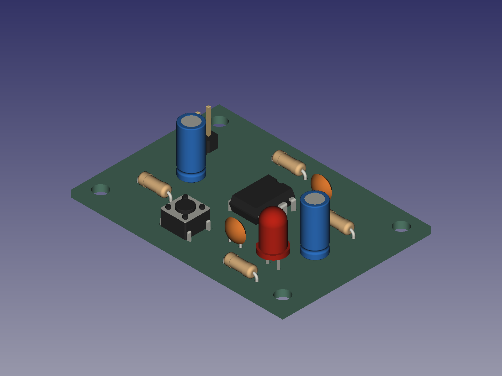
regulated input at J1 feeding a TLC555CP in an astable configuration.
nominal frequency and 52.4% nominal duty cycle; component tolerances affect the result.
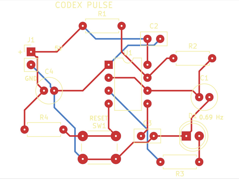
two copper layers, 1.6 mm board thickness and four 3.2 mm non-plated mounting holes.
The workflow
From electrical intent to files a manufacturer can inspect
The project was built from scratch around the Texas Instruments TLC555CP and datasheet SLFS043K. The requirement became an astable circuit driving a red LED through 1 kΩ, with reset button, supply and control-pin decoupling, polarity markings and four mounting holes.
- Bound voltage, function, timing, components, mechanics and test limitations.
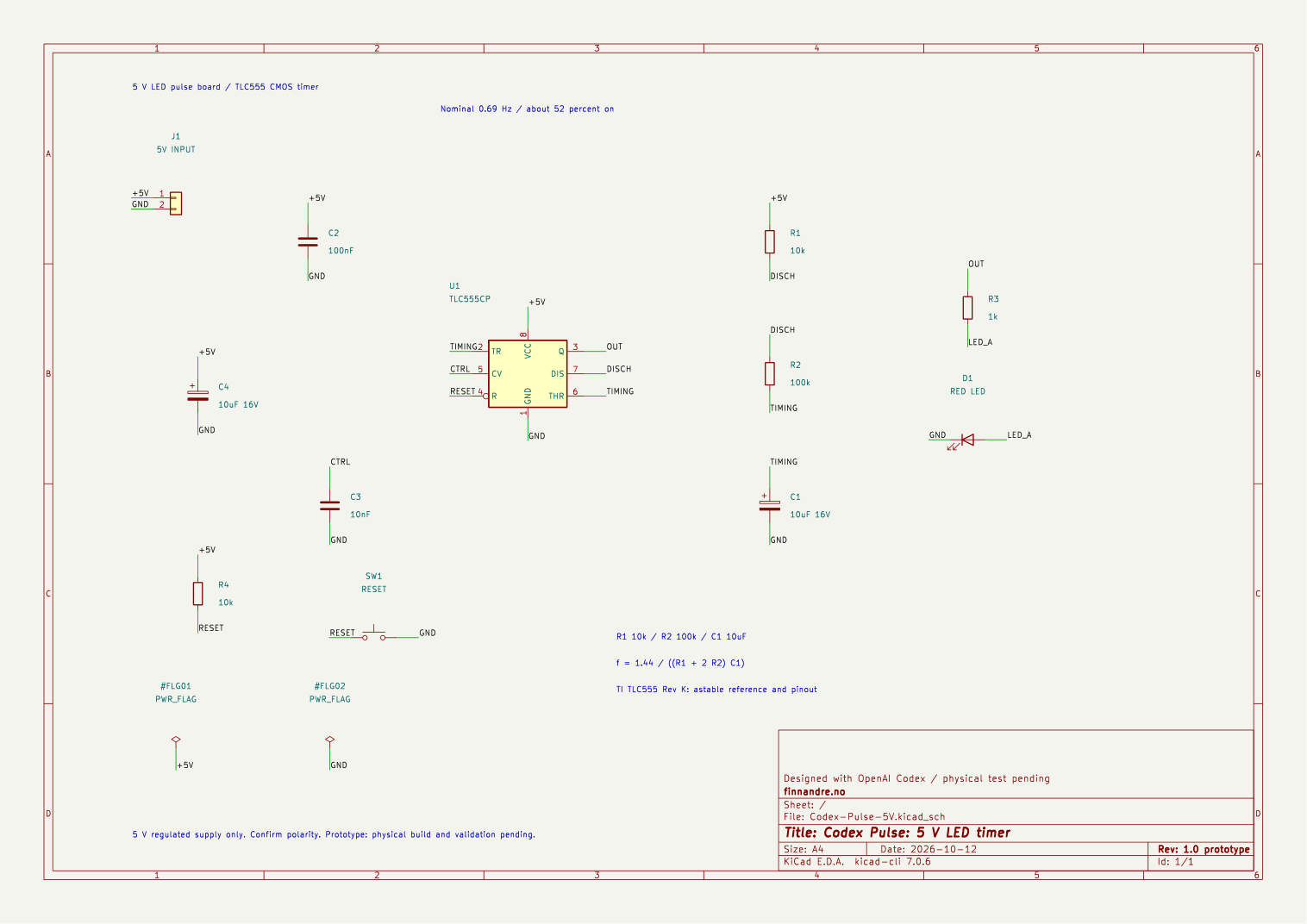
- Create the schematic and netlist; compare 30 electrical pins across eight nets.
- Assign footprints, place and route two layers using 0.30 mm tracks and 0.25 mm requested clearance.
- Run DRC, reopen the PCB and export Gerbers, PTH/NPTH drills, BOM and STEP.
Worked example
How the 5 V LED requirement became a schematic and PCB
The starting point was a simple repeatable signal: regulated 5 V input, a visible LED pulse and a reset button. Codex used the TLC555 datasheet’s astable circuit as the source basis, not an arbitrary web example. The timing network was set to R1 = 10 kΩ, R2 = 100 kΩ and C1 = 10 µF.
The nominal frequency follows f ≈ 1.44 / ((R1 + 2 × R2) × C1). With those values it is approximately 0.686 Hz. Nominal duty cycle follows (R1 + R2) / (R1 + 2 × R2), or approximately 52.38%. These are calculated nominal values; resistor and capacitor tolerance, supply and the real component affect measured performance.
The LED received a 1 kΩ series resistor. Reset received a 10 kΩ pull-up, and the supply and control pin received decoupling. Components and pins were then written into the native KiCad schematic and connectivity structure. The exported netlist was compared with the design record before matching footprints were placed in pcbnew.
The board script and KiCad tools created the outline, mounting holes, placement, copper layers and routing. The native PCB was reopened, DRC was run, and Gerbers, PTH/NPTH drills, BOM and the component STEP were exported. This documents a repeatable toolchain from requirement to files; it does not document a physically assembled board.
Observed software checks
What passed
- Native schematic and netlist export: pass.
- Schematic versus design record: 30 electrical pins across eight nets.
- PCB-to-schematic pin/net comparison: pass.
- Native PCB reopen: pass.
- KiCad DRC: 0 violations, 0 unconnected pads and 0 footprint errors.
- STEP readback: 13 valid solids.
Important boundary
What was not tested
- Native ERC was not run because the recorded KiCad 7.0.6 CLI did not expose that command.
- The board has not been built, powered or timed.
- Purchased-part fit, polarity, soldering and physical assembly are unconfirmed.
- No fabrication order or manufacturer approval is claimed.
What you can inspect
Native files and fabrication-oriented outputs
| Deliverable | Purpose | Public link |
|---|---|---|
.kicad_pro, .kicad_sch, .kicad_pcb |
Editable native project, schematic and PCB. | Project directory |
| BOM and netlist | Component inventory and machine-readable connectivity. | BOM.csv / NETLIST.xml |
| Gerbers + drills | Copper, mask, silkscreen, outline, PTH and NPTH. | Gerber directory |
| STEP | Mechanical component view for further inspection. | Codex-Pulse-5V.step |
| DESIGN / VERIFICATION / STEP-READBACK | Structured, bounded verification record. | JSON evidence |
Project-local footprint copies come from the official KiCad libraries and retain their original licence boundary. Original project code and documentation are MIT licensed.
Before physical fabrication
Move from open evidence to your own verification
Open the project in a supported KiCad release. Check the datasheet, TLC555CP package and pin 1, C1/C4 polarity, resistor and capacitor tolerances, footprints against the parts you will purchase, your manufacturer’s design rules, and the generated Gerber and drill files. Rerun ERC and DRC in your environment. Only physical assembly and measurement can confirm electrical operation and timing.
The 87-second Codex Pulse film is now public on YouTube and maps to the same open project source. The archived original master was not restored merely to create another release asset.
OpenAI Codex is credited as a working tool. This independent project is not sponsored, certified or endorsed by OpenAI, KiCad or Texas Instruments.
New complete workflow · 13 October 2026
From four logic ICs to enclosure, firmware and MQTT
The second open KiCad project uses two 74HCT164 shift registers, a 74HCT688 address comparator and a 74HCT273 output latch. Eight low-current LEDs show output state, while 1, 2, 4 and 8 weighted jumpers select an address. The public directory contains native schematic and PCB files, BOM, netlist, Gerbers and drills, STEP, FreeCAD assembly and enclosure, STL, a firmware example, web demo, MQTT protocol and verification results.
Watch the ten-minute walkthrough on YouTube, or open the exact public source commit. The film is also available as a hash-verified release asset.
Boundary: DRC 0/0/0, 65,536 ideal protocol frames, FreeCAD geometry readback and local MQTT with two clients were observed. ESP32/GPIO and electrical hardware are simulated; firmware remains uncompiled and unflashed, while ERC, assembly and physical electrical, thermal and RF testing remain.
Frequently asked questions
Does zero DRC errors mean that the circuit works?
No. DRC checks defined layout rules and connectivity. It does not replace ERC, datasheet review, physical assembly or electrical measurement.
Can the Gerbers go directly to fabrication?
They are published for inspection and learning. Check them against your manufacturer, actual parts and responsibility before placing any order.
Why publish an unbuilt project?
Open native files and explicit unknowns are more inspectable than a broad claim that AI can design a PCB. Others can review, learn from and improve the work.